DIY 6DOF Motion Platform - Platform Controller with Thanos Board
I did a lot of tests with the thanos board, but i was first not able to get it to work properly. There were random "kicks" during movement of the platform. I did not find the cause. But after tests with the 2.0 software-release of the thanos board i believe it has something to do with the thanos board, because the "kicks" went away. First i thought it has something to do with the analog connection between the feedback sensors and the thanos board and the analog connections between the thanos board and the sabertooths. I used shielded and grounded cables everywhere, but the kicks remain. It could be noise caused by the motors, but i was unable to detect it.
However: it works now and is usable.
|
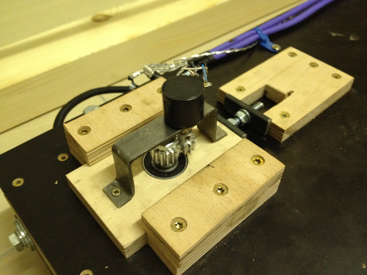
Test with new mounted pots (in combination with the encoders) directly at the motors.

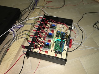
Thanos-board-housing with sabertooth-controllers. Over the last few weeks i did some tests with the thanos-board and the new 2.0 release. To do this i installed the thanos-board with new sabertooth-controllers in a new housing. It seems to run better (and without noise) than the previous versions.
Movie of the running platform, driven by fsx and the thanos board (old first housing):
|
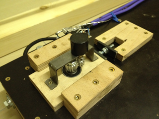
Mounted analog feedback sensor.
Wiring information:

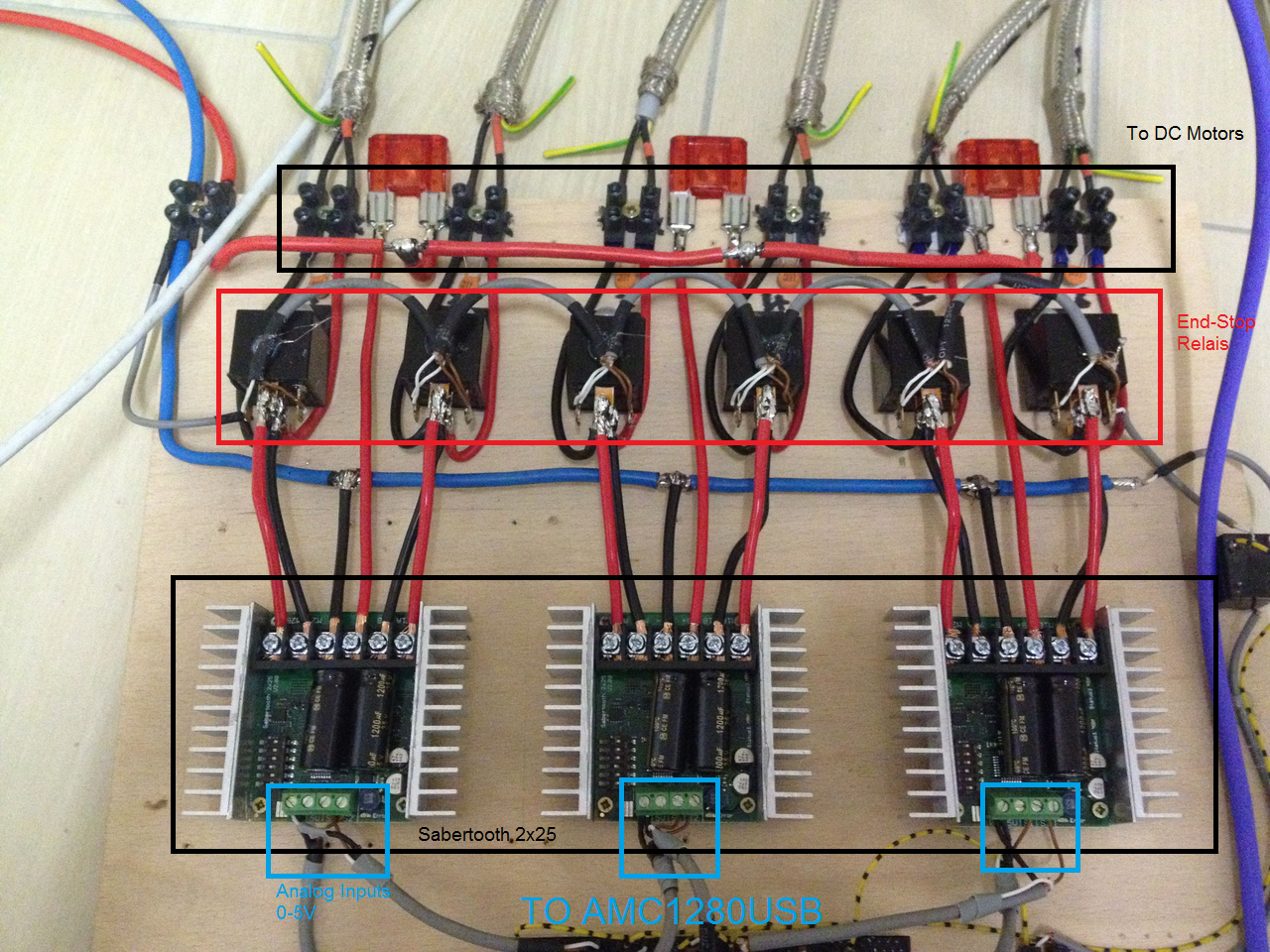
This image above shows the wirings of the sabertooth 2x25 motor controllers. On the lower side the position demand signals arrive, on the upper side the 6 actuators are connected. I added 6 end-stop relais to provide safety in case of some actuator problem (the relais are triggered by end-stop switches installed on the actuators). The red items on the upper side are 50 amp fuses. Click on the image to view a larger image.
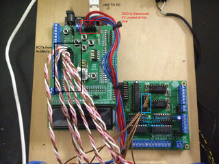
The image above shows the connections from and to the AMC1280USB+6DOF board. On the left side the position feedback sensors (pots) are connected. The brown cables provide the position demand signals for the sabertooth controllers. The GND for the sabertooth is the blue cable from the upper side. The red one is unused. Click on the image to enlarge.

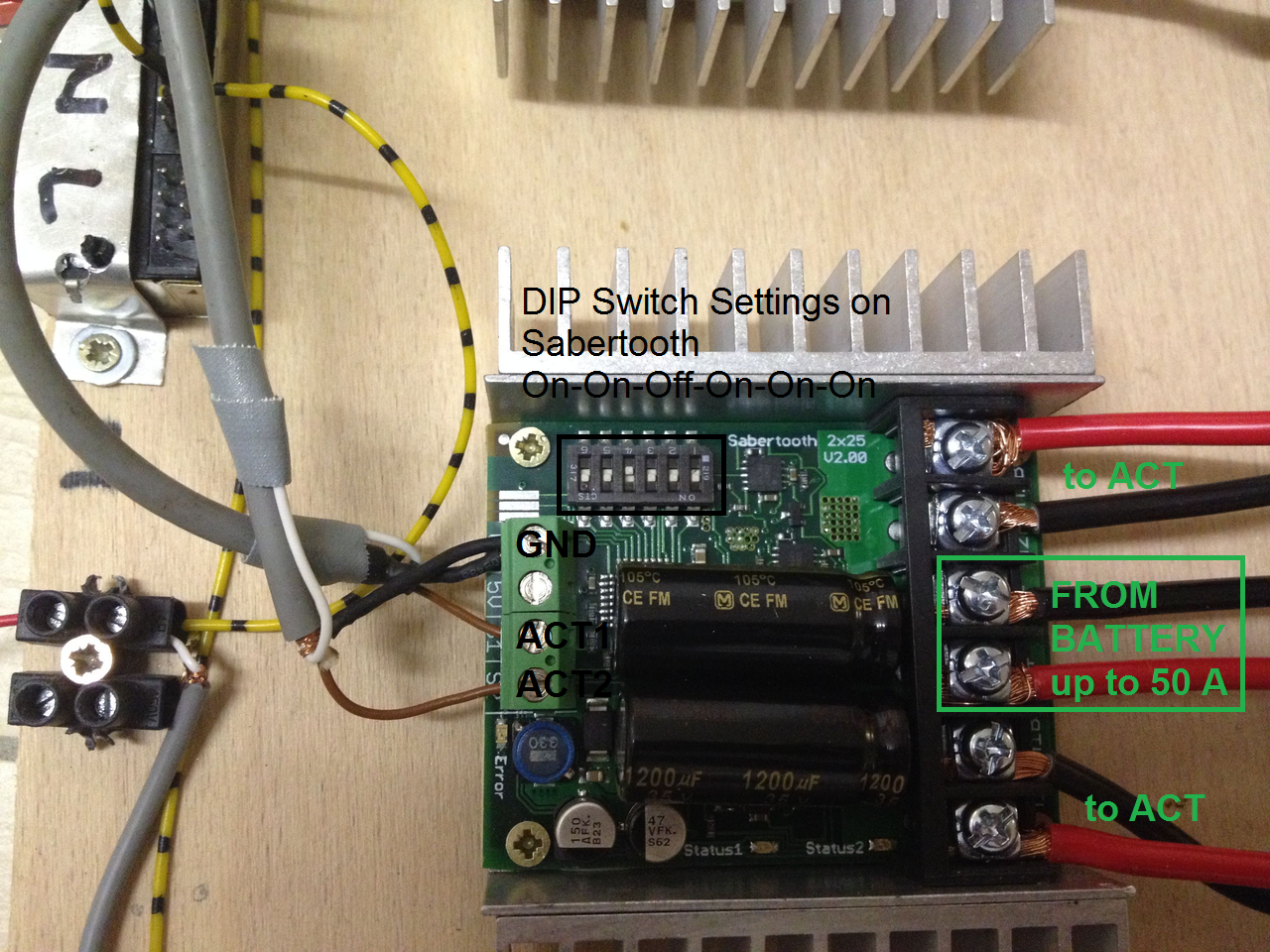
The image shows detailed information about the sabertooth settings. The dip-switches must be set to on-on-off-on-on-on to configure them for analog input. On the right side the power from the batteries and the 2 actuators are connected. On the left side the position demand signals (from the amc) and gnd are connected.